Wedge Barriers Can Be Fun For Anyone
Table of ContentsFacts About Wedge Barriers RevealedAll About Wedge Barriers
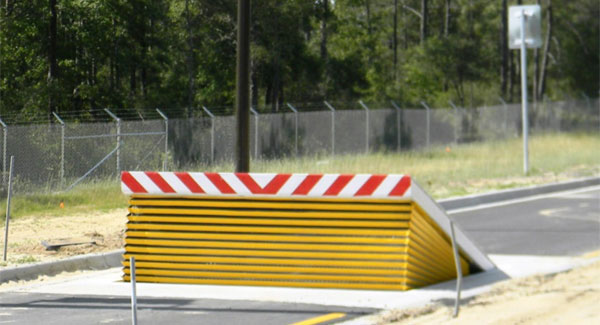
14 and the surface 12 to which the barrier 10 is protected may be made from concrete - Wedge Barriers. 2, the obstacle 10 is installed to or includes a support or subframe (e. g., anchor 30 received FIG. 2 )secured below the surface area 12. The bather 10 might be bolted to the support or protected to the anchor by various other mechanical bolts. In the detailed personification, the barrier 10 includes a wedge plate 16, which includes a section that is considerably parallel with the surface 12 when the barrier 10 remains in the withdrawed position. In various other words, lorries or individuals might overlook the obstacle 10 when the barrier 10 remains in the pulled back position and experience small elevation relative to the surface 12 while on the obstacle 10. As discussed in information listed below, when the barrier 10 remains in the deployed position, the wedge plate 16 is held and supported in a raised setting by a lifting device of the obstacle 10. Additionally, the parts 18 may be bolted or otherwise mechanically combined to one another. In this manner, fixing or substitute of several components 18 might be simplified and structured. That is, repair service or replacement of solitary parts
18 may be done a lot more swiftly, easily, and expense effectively. FIG. In particular embodiments, the anchor 30 might be a steel structure including plates, beam of lights(e. g., I-beams ), and/or other frameworks that are protected within the foundation 14, which may be concrete. At the surface area 12, an upper side 28 of the support 30 might be at least partly revealed
, thereby enabling the attachment of the obstacle 10 to the anchor 30. g., threaded openings)in one or even more beam of lights or plates of the support 30 might be exposed to the surface 12. In this way, screws 32 or various other mechanical bolts might be utilized to protect the obstacle 10 to the support 30. As the obstacle 10 is mounted to the surface area 12 of the structure 14, collection of particles and various other material beneath the obstacle may be lowered, and parts of the bather 10 may not be exposed to below grade settings. As shown by recommendation character 52, the lifting mechanism 50 consists of parts got rid of underneath the wedge plate 16. For instance, the parts 52 beneath the wedge plate 16 may consist of an electromechanical actuator, a cam, several cam surface areas, etc. Furthermore, the training device 50 includes a springtime assembly 54
The springtime rod 58 is paired Discover More Here to a camera(e. g., web cam 80 received FIG. 4) of the training mechanism 50. The springtimes 60 disposed concerning the spring rod 58 are kept in compression by springtime supports 62, consisting of a fixed springtime support 64. That is, the fixed spring support 64 is taken care of about the structure 14 and the remainder of the bather 10.
3 Easy Facts About Wedge Barriers Described
g., spring support 65 )may be repaired to the end of the spring rod 58 to make it possible for compression of the springs 60. As the springs 60 are pressed between the springtime sustains 62, the springtime setting up 54 generates a force acting upon the cam combined to the springtime rod 58 in an instructions 66. For instance, the staying pressure related to
the camera to deploy the wedge plate 16 may be offered by an electromechanical actuator 84 or various other actuator. The spring setting up 54 and the actuator 84(e. g., electromechanical actuator)might operate together to convert the web cam and lift the wedge plate 16.
As pointed out above, the spring setting up 54 applies a continuous force on the cam, while the electromechanical actuator may be regulated to apply a variable pressure on the webcam, consequently making it possible for the lifting and decreasing( i. e., releasing and retracting )of the wedge plate 16. In particular embodiments, the continuous pressure applied by the springtime setting up 54 may be adjustable. g., electromechanical actuator) is disabled. As will certainly be appreciated, the springtime assembly 54 may be covered and safeguarded from debris or various other elements by a cover his explanation plate(e. g., cover plate 68 received FIG. 4) that might be substantially flush with the raised surface area 38 of the foundation 14. As pointed out above, in the released setting, the wedge plate 16 offers to block accessibility or travel beyond the obstacle 10. For instance, the obstacle 10(e. g., the wedge plate 16 )may obstruct pedestrians or vehicles from accessing a home or pathway. As discussed above, the obstacle 10 is connected to the support 30 protected within the foundation 14,

front braces 71. Therefore, the linkage assemblies 72 may pivot and revolve to make it possible for the collapse and expansion of the linkage settings up 72 throughout retraction and release of the bather 10. The affiliation settings up 72 reason activity of the wedge plate 16 to be limited. If a car is taking a trip towards the released wedge plate 16(e. For instance, in one scenario, the security legs 86 may be expanded duringmaintenance of the barrier 10. When the security legs 86 are released, the safety and security legs 86 sustain the weight of the wedge plate 16 versus the surface area 12. Because of this, the training device 50 may be shut off, serviced, gotten rid of, replaced, etc. FIG. 5 is partial viewpoint view of an embodiment of the surface-mounted wedge-style barrier 10, illustrating the camera 80 and the webcam surfaces 82 of the training mechanism 50. Especially, 2 webcam surfaces 82, which are referred to as lower cam surfaces 83, are positioned below the webcam 80. The reduced web cam surfaces 83 may be taken care of to the surface 12 (e. For example, the lower cam surfaces 83 and the installing plate 85 may develop a single piece read more that is safeguarded to the anchor 30 by screws or various other mechanical fasteners. In addition, 2 camera surface areas 82, which are referred to as upper cam surface areas 87, are placed above the camera 80 and paired to (e. In various other embodiments, intervening layers or plates might be positioned in between the surface area 12 and the lower cam surface areas 83 and/or the wedge plate 16 and the top camera surface areas 87 As pointed out above, the web cam
80 equates along the camera surfaces 82 when the wedge plate 16 is raised from the retracted setting to the released setting. In addition, as mentioned over, the spring assembly 54 (see FIG. 3 )might provide a pressure acting upon the cam 80 in the direction 102 using springtime rod 58, which may minimize the pressure the electromechanical actuator 84 is called for to put on the cam 80 in order to activate and raise the wedge plate 16. 1 )to the released setting(see FIG. 4). As shown, the webcam 80 consists of track wheels 104(e. g., rollers), which contact and equate along the cam surface areas 82 throughout operation.